This CCNA study guide covers Cisco exam 200-301 CCNA v2.0, Implementing and Administering Cisco Solutions. It works through Cisco’s published exam topics one domain at a time, in Cisco’s order, with plain-English definitions, comparisons of the ideas that are easy to mix up, and reference tables where a table is faster than prose. It is free to read and needs no sign-up.
The version matters. According to Cisco’s Learn with Cisco blog, the last day to test on CCNA v1.1 is February 2, 2027, and v2.0 goes live for testing on February 3, 2027. This guide covers v2.0. Anyone with an exam booked before February 3, 2027 sits v1.1 and should study from Cisco’s CCNA v1.1 exam topics instead.
Sources: the domains, weights and topics come from Cisco’s CCNA v2.0 exam topics; exam length, price and languages from Cisco’s 200-301 exam page; prerequisites and validity from Cisco’s CCNA certification page. Technical details link to a Cisco guide, IETF RFC, IEEE standard or other primary source where they appear.
In this guide
- CCNA 200-301 v2.0 at a glance
- What’s changing
- How to use this guide
- Domain 1: Network Infrastructure and Connectivity
- Domain 2: Switching and Network Access
- Domain 3: IP Routing
- Domain 4: Network Services and Security
- Domain 5: AI, and Network Operations and Management
- A study plan
- Practice questions
- Frequently asked questions
- Sources
CCNA 200-301 v2.0 at a glance
| Exam | Implementing and Administering Cisco Solutions (200-301 CCNA) v2.0 |
|---|---|
| Certification earned | CCNA |
| Time | 120 minutes |
| Number of questions | Not listed on Cisco’s exam page |
| Passing score | Not published; Cisco’s CCNA page describes the exam as graded pass/fail |
| Price | US$300, or Cisco Learning Credits (as of November 2026) |
| Languages | English and Japanese, per Cisco’s exam page (as of November 2026) |
| Prerequisites | None |
| Certification valid for | Three years |
| Last day to test on v1.1 | February 2, 2027 |
| First day to test on v2.0 | February 3, 2027 |
Cisco’s exam description adds two points worth knowing. Candidates may be asked to weigh the suggestions and output that agentic AI tools and digital network assistants produce during operations and troubleshooting work. And the topic list is a general guide: related topics can appear on any given exam, and Cisco can change the list without notice.
What’s changing
Checked against Cisco’s pages on November 15, 2026.
- February 2, 2027: the last day to test on 200-301 CCNA v1.1.
- February 3, 2027: CCNA v2.0 goes live for testing. Cisco describes it as a change in depth rather than a total overhaul, with more practical assessment, security and AI throughout, and more troubleshooting (Cisco, July 1, 2026).
If you test on or before February 2, 2027, you sit v1.1. Key dates and which version you’ll sit: CCNA v2.0 start date and v1.1 last test date.
For every upcoming exam date, see the IT certification exam calendar.
How to use this guide
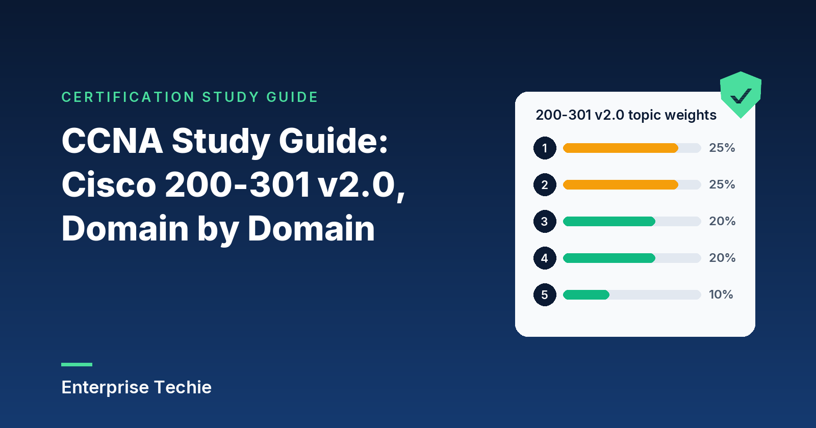
The guide follows Cisco’s five domains in order, with one section per exam topic. The weights tell you where the points are: the first two domains together are half the exam.
| Domain | Share of exam | Topics |
|---|---|---|
| 1.0 Network Infrastructure and Connectivity | 25% | 7 |
| 2.0 Switching and Network Access | 25% | 5 |
| 3.0 IP Routing | 20% | 4 |
| 4.0 Network Services and Security | 20% | 7 |
| 5.0 AI, and Network Operations and Management | 10% | 6 |
| Total | 100% | 29 |
For a shorter map of the same list, with every topic summarized in a line or two, see CCNA exam topics explained. To test yourself as you go, try the free CCNA practice questions.
Domain 1: Network Infrastructure and Connectivity (25%)
The physical and addressing groundwork: cables and interfaces, virtualization, IPv4 and IPv6, wireless, client troubleshooting and DHCP. Five of the seven topics begin with Troubleshoot or Diagnose, so expect to reason from symptoms back to causes.
1.1 Diagnosing copper and fiber interface and cable problems
Interface faults show up first in the counters of show interfaces. Cisco’s switch port troubleshooting guide defines them:
| Counter | What it counts |
|---|---|
| CRC / FCS errors | Frames that arrived with a bad frame check sequence |
| Runts | Frames under the 64-byte Ethernet minimum, with a bad CRC |
| Giants | Frames over the 1518-byte maximum for non-jumbo Ethernet |
| Late collisions | Collisions detected late in the transmission |
Cisco’s advice is to set both ends of a link the same way: both auto-negotiating speed and duplex, or both set manually. A duplex mismatch brings slow performance, intermittent connectivity and dropped connections. When FCS, CRC, alignment or runt counters climb, rule out a mismatch first; late collisions from a mismatch appear on the half-duplex side.
Copper. Cisco’s cable specifications give a maximum segment of 100 m (328 ft) for 10BASE-T and 100BASE-TX. On those links, pins 1 and 2 transmit and pins 3 and 6 receive. A straight-through cable keeps the wire order at both ends and suits unlike devices (switch to router); a crossover swaps the pairs and suits like devices (switch to switch). Catalyst 9300 switches enable Auto-MDIX by default to detect the cable type, but it works only when speed is set to autonegotiate.
Fiber. Cisco’s 1000BASE-SX optic uses 850 nm light and reaches up to 550 m on 50 µm multimode fiber; the 1000BASE-LX/LH optic uses 1310 nm and reaches up to 10 km on single-mode fiber. Optics and cable on a link must match, all multimode or all single-mode. show interfaces <id> transceiver detail reports optical power in dBm beside the module’s thresholds, and Cisco’s fiber troubleshooting guide treats readings outside the warning thresholds as a problem that can cause the link to flap.
Exam tip: late collisions point to a duplex mismatch and show on the half-duplex end. CRC errors have more possible causes, so check duplex, then the cable.
1.2 What hypervisors, virtual machines and containers do
NIST’s SP 800-125 describes the hypervisor, or virtual machine monitor, as the layer that manages guest operating systems and controls their access to CPU, memory, storage and network cards. In bare metal virtualization it runs directly on the hardware; in hosted virtualization it runs on top of a host OS. IBM uses the common labels Type 1 (on the hardware) and Type 2 (hosted).
| Virtual machine | Container | |
|---|---|---|
| Contains | A complete guest OS plus the app | The app and its files, sharing the host’s kernel |
| Isolation | Hardware-level, enforced by the hypervisor | Weaker, because containers share a kernel |
| Operating systems | Linux and Windows can share one host | Same OS family as the host |
The container column comes from NIST’s SP 800-190, which adds that an orchestrator turns container images into running containers on hosts. VMs and containers still need addresses and VLANs, which is why topic 2.2 lists virtualized hosts as a switch port type.
Exam tip: a Type 2 hypervisor needs a host OS underneath it; a container needs a host kernel of its own OS family.
1.3 Troubleshooting IPv4 addressing and subnetting
Most IPv4 faults come down to four settings: address, mask, default gateway and DNS server. The reserved ranges to recognize on sight: the private blocks 10.0.0.0/8, 172.16.0.0/12 and 192.168.0.0/16 (RFC 1918); link-local 169.254.0.0/16, which a host assigns itself when no DHCP server answers (RFC 3927); and loopback 127.0.0.0/8 (RFC 1122). Examples here use the documentation block 192.0.2.0/24 (RFC 5737).
Subnetting. RFC 1122 does not allow an all-zeros or all-ones host field, so a subnet with h host bits has 2h minus 2 usable addresses. The exception is a /31 on a point-to-point link, where RFC 3021 makes both addresses usable.
| Prefix | Mask | Usable hosts |
|---|---|---|
| /24 | 255.255.255.0 | 254 |
| /25 | 255.255.255.128 | 126 |
| /26 | 255.255.255.192 | 62 |
| /27 | 255.255.255.224 | 30 |
| /28 | 255.255.255.240 | 14 |
| /29 | 255.255.255.248 | 6 |
| /30 | 255.255.255.252 | 2 |
A worked example: a host set to 192.0.2.77/26 sits in 192.0.2.64/26, because /26 blocks start every 64 addresses. Its broadcast is 192.0.2.127 and its usable range .65 to .126. A default gateway of 192.0.2.1 lies outside that subnet, so the host cannot reach it. Checking that the gateway is inside the host’s own subnet is a fast first step on any IPv4 ticket; a wrong mask and a duplicate address are the next suspects.
Exam tip: 169.254.x.x means the host gave up on DHCP. 10.x, 172.16 to 172.31 and 192.168 addresses are private but valid assignments.
1.4 Troubleshooting IPv6 addressing and prefix sizing
RFC 4291 writes an IPv6 address as eight 16-bit groups of hex. Leading zeros in a group can be dropped, and one run of zero groups can become ::, which may appear only once. There are no broadcast addresses; multicast does that job.
| Type | Prefix | Notes |
|---|---|---|
| Global unicast | 2000::/3 | IANA’s current unicast assignments (IANA) |
| Unique local | fc00::/7 | Not expected to route on the internet (RFC 4193) |
| Link-local | fe80::/10 | One link only; routers do not forward packets from link-local sources (RFC 5340) |
| Multicast | ff00::/8 | Replaces broadcast |
Prefix sizing. RFC 4291 requires 64-bit interface IDs for unicast addresses outside the binary 000 range, so LAN subnets are /64. RFC 6164 covers /127 on router-to-router links, and a single-host route is /128.
Modified EUI-64. Split the 48-bit MAC in half, insert FFFE in the middle, and invert the universal/local bit. MAC 00:1A:2B:3C:4D:5E becomes interface ID 021A:2BFF:FE3C:4D5E (the bit flip turns 00 into 02), so on 2001:db8:acad:1::/64 (a documentation prefix) the address is 2001:db8:acad:1:21a:2bff:fe3c:4d5e.
Assignment. With SLAAC (RFC 4862), a host learns prefixes from Router Advertisements, appends an interface ID, and runs Duplicate Address Detection first. DHCPv6 (RFC 9915) uses Solicit, Advertise, Request and Reply, with clients on UDP 546 and servers on UDP 547. IPv6 addressing leans on Neighbor Discovery (RFC 4861): Router Solicitation and Router Advertisement (ICMPv6 types 133 and 134), Neighbor Solicitation and Neighbor Advertisement (135 and 136, which resolve link-layer addresses and drive Duplicate Address Detection), and Redirect (137).
A host with only a link-local address has not formed a global one. Check that Router Advertisements arrive and that the router forwards IPv6 at all, since ipv6 unicast-routing is what enables IPv6 unicast forwarding on IOS XE (Cisco).
Exam tip: fe80::/10 link-local works only on the local link. fc00::/7 unique local can cross an organization’s routers but is not meant for the internet.
1.5 Wireless principles: bands, RF, security and interference
Bands and channels, from Cisco’s Wireless RF Reference Guide: 2.4 GHz defines 14 channels, but only 3 do not overlap, and in the US those are 1, 6 and 11. The 802.11 standard defines 23 channels of 20 MHz in 5 GHz. The 6 GHz band runs from 5925 to 7125 MHz with 59 channels of 20 MHz. Wi-Fi 6E extends Wi-Fi 6 (802.11ax) into 6 GHz, and Wi-Fi 7 (IEEE 802.11be) uses 2.4, 5 and 6 GHz with channels up to 320 MHz wide.
RF characteristics. Received signal strength is a negative dBm value, so closer to zero is stronger; Cisco notes that -66 dBm is often used as the target when surveying client coverage. Signals weaken with distance and through materials (attenuation, measured in dB), depending on metal, moisture, thickness and conductivity. Reflections create multipath, copies of the signal that can add to, subtract from or distort it.
| Security mode | Authentication | Notes |
|---|---|---|
| WPA2-Personal | Pre-shared key (PSK) | AES with CCMP-128 |
| WPA3-Personal | Simultaneous Authentication of Equals (SAE) | Better protection against password guessing |
| WPA3-Enterprise | IEEE 802.1X | Optional 192-bit mode using GCMP-256 |
| Enhanced Open (OWE) | None; the network is open | Encrypts traffic on open networks |
Sources: Cisco’s WPA3 Deployment Guide, which also makes Protected Management Frames mandatory for WPA3; the Wi-Fi Alliance, which requires WPA3 for Wi-Fi CERTIFIED devices; and IEEE 802.1X, port-based access control. WPA3 transition mode lets WPA3 clients use SAE while WPA2 clients use PSK on the same network.
Interference. Co-channel interference comes from nearby radios on the same channel; adjacent channel interference comes from channels that overlap. Non-Wi-Fi sources in Cisco’s list include microwave ovens, baby monitors, Bluetooth devices and cordless phones.
Exam tip: sticking to 1, 6 and 11 removes overlap in 2.4 GHz, but two nearby APs that both use channel 6 still cause co-channel interference.
1.6 Troubleshooting wired and wireless clients on Windows, macOS and Linux
Work from the bottom up: address, mask, gateway and DNS server; reachability to the gateway, then the remote host; name resolution; and on Wi-Fi, matching SSID and security settings.
| Platform | Commands and tools |
|---|---|
| Windows | ipconfig /all (full configuration), ipconfig /release and /renew (DHCP lease), ipconfig /flushdns, tracert, nslookup, netsh wlan show interfaces |
| macOS | Wireless Diagnostics: Option-click the Wi-Fi icon; it analyzes the connection and lists detected issues |
| Linux | ip addr (addresses), ip route (routing table), nmcli device status, nmcli device wifi list (visible access points) |
Sources: Microsoft Learn (ipconfig, tracert, nslookup, netsh wlan), Apple Support, ip(8) and nmcli. Microsoft notes that ipconfig shows whether settings came from DHCP or Automatic Private IP Addressing, its name for the 169.254 range.
If a client sees the SSID but cannot join, compare security settings: the passphrase, whether the client supports the network’s mode (a WPA2-only client cannot use SAE unless the network runs transition mode), and for 802.1X, the user’s credentials.
Exam tip: a 169.254 address points to DHCP. A correct address with no default gateway reaches its own subnet and nothing beyond it.
1.7 Troubleshooting DHCPv4 clients, servers and relays on IOS
DHCP runs in four messages, often remembered as DORA (RFC 2131): the client broadcasts a DHCPDISCOVER, servers answer with a DHCPOFFER, the client sends a DHCPREQUEST for one offer, and the server confirms with a DHCPACK. Clients send to UDP port 67, and servers reply to port 68.
IOS XE as the server. Cisco’s DHCP server guidance builds one pool per subnet: ip dhcp excluded-address 192.0.2.1 192.0.2.10 keeps fixed addresses out, then ip dhcp pool LAN with network, default-router, dns-server and lease. show ip dhcp binding lists leases and show ip dhcp pool shows addresses assigned and available. The server needs a Layer 3 interface, such as an SVI, in the client subnet, and Catalyst 9000 switches need service dhcp enabled to act as server or relay (Cisco).
Relay. A server on another subnet needs a relay agent, a router that passes DHCP messages between clients and servers. On IOS XE, ip helper-address <server> goes on the interface facing the clients, usually the SVI. The relay writes its own address into the giaddr field, and the server picks the client’s address based on it (RFC 2131). debug ip dhcp server packet detail shows the exchange, and a ping from the relay to the server checks unicast reachability.
Exam tip: the helper address goes on the interface where the clients live, not on the interface facing the server.
Domain 2: Switching and Network Access (25%)
How switches connect to each other, to routers and to end devices, and how spanning tree keeps the Layer 2 topology loop-free. Five topics; three begin with Configure, so know the commands as well as the concepts.
2.1 Configuring switch-to-switch and switch-to-router links
Layer 2 and Layer 3 interfaces. Cisco’s interface guide separates three port types. An access port carries one VLAN (plus a voice VLAN if configured). A trunk port carries many VLANs and by default belongs to all of them. A routed port is a physical port put into Layer 3 mode with no switchport; it acts like a router interface.
VLANs. A VLAN segments a switched network logically, broadcasts stay inside it, and traffic between VLANs must be routed. Normal-range VLANs are 1 to 1005 and extended-range VLANs are 1006 to 4094. VLAN 1 and VLANs 1002 to 1005 are created automatically and cannot be removed.
802.1Q trunks. Catalyst switches trunk with IEEE 802.1Q, the industry-standard encapsulation. According to Cisco’s trunk configuration guide, a trunk allows VLANs 1 to 4094 by default, and untagged traffic belongs to the native VLAN, VLAN 1 unless changed. Use switchport mode trunk, switchport trunk allowed vlan and switchport trunk native vlan, and check with show interfaces <id> trunk. Both ends should agree on the native VLAN, because each side drops untagged frames into its own native VLAN.
| Switchport mode | Behavior (Dynamic Trunking Protocol) |
|---|---|
trunk | Permanent trunk; also negotiates the neighbor into trunking |
dynamic desirable | Actively tries to trunk; trunks with trunk, desirable or auto |
dynamic auto (default) | Trunks only if the neighbor is trunk or desirable |
nonegotiate | Stops the port sending DTP frames |
EtherChannel with LACP. Cisco’s EtherChannel guide describes bundling up to eight compatibly configured Ethernet ports into one logical link; with LACP, up to eight more can wait in standby. Cisco’s guide cites IEEE 802.3ad for LACP; the IEEE now publishes link aggregation as IEEE 802.1AX.
| Mode | Protocol | Behavior |
|---|---|---|
| active | LACP | Starts negotiation |
| passive | LACP | Answers LACP packets but never starts |
| desirable | PAgP (Cisco-proprietary) | Starts negotiation |
| auto | PAgP | Answers only if a PAgP device is detected |
| on | None | Forces the channel with no negotiation; both ends must match |
A channel forms only when at least one side starts the negotiation. Member ports need the same speed, duplex and VLAN or trunk settings; a Layer 3 EtherChannel uses no switchport. channel-group <n> mode <mode> adds a port, and show etherchannel summary shows the result.
SVIs. A switch virtual interface represents a VLAN to the switch’s routing function: interface vlan 10 with an IP address becomes the gateway for VLAN 10. On the Catalyst 9300, IP routing is disabled by default and enabled with ip routing (Cisco).
Exam tip: two ports left at dynamic auto each wait for the other to ask, so no trunk forms. The same logic applies to LACP passive on both ends.
2.2 Configuring edge ports for hosts, phones, access points and appliances
Edge ports connect end devices. The device types in this topic map to a handful of port patterns:
| Device | Typical port setup |
|---|---|
| Desktop, printer, IoT appliance | Access port in one VLAN, with PortFast for a single end station |
| IP phone with a PC behind it | Access VLAN for the PC plus a voice VLAN for the phone |
| Access point in local mode (controller-based) | Access port with PortFast; Cisco’s best-practices guide says the port can be set directly to access mode |
| Access point in FlexConnect with locally switched WLANs | Trunk, pruned to the VLANs the AP uses |
| Standalone access point | Access port for one VLAN; a trunk if its SSIDs map to several VLANs |
| Virtualized host | Trunk carrying the VMs’ VLANs, optionally bundled with LACP |
| Network appliance | Access port, trunk or port channel, depending on how many VLANs it serves |
For controller-based APs, Cisco’s Catalyst 9800 best practices recommend PortFast on AP switch ports and note that the controller’s wireless management interface terminates all the CAPWAP traffic from APs.
Voice VLAN. The voice VLAN feature lets an access port carry IP phone traffic. Configure switchport access vlan for the PC and switchport voice vlan for the phone. The phone tags voice in the voice VLAN with a CoS value (5 by default on Cisco phones), while untagged traffic from the attached PC passes through the phone unchanged. CDP must be enabled on the port to send the configuration to the phone.
PoE. From Cisco’s Catalyst 9300 PoE guide:
| Standard | Name | Power per port |
|---|---|---|
| IEEE 802.3af | PoE | 15.4 W |
| IEEE 802.3at | PoE+ | 30 W |
| IEEE 802.3bt Type 3 | Cisco UPOE class | 60 W |
| IEEE 802.3bt Type 4 | Cisco UPOE+ class | 90 W |
The default power inline auto mode detects a powered device and grants power if the switch’s power budget allows. show power inline shows PoE status per switch or interface.
Exam tip: on a phone port, the voice VLAN carries the phone’s tagged traffic and the access VLAN carries the PC’s untagged traffic, both on the same physical port.
2.3 Checking network documentation with CDP and LLDP
Diagrams go stale. CDP and LLDP let each device report its directly connected neighbors, so the documentation can be checked against what the cables actually connect.
| CDP | LLDP | |
|---|---|---|
| Origin | Cisco; runs on Cisco-manufactured devices | IEEE 802.1AB, for multivendor networks |
| Layer | Layer 2, media-independent | Layer 2 neighbor discovery |
| Default on Catalyst 9300 | Enabled globally and per interface | Disabled |
| Advertisement timer | 60 seconds | 30 seconds |
| Holdtime | 180 seconds | 120 seconds |
| Turn on | cdp run, cdp enable | lldp run, then lldp transmit and lldp receive |
| View neighbors | show cdp neighbors [detail] | show lldp neighbors |
Sources: Cisco’s CDP and LLDP configuration guides and the IEEE 802.1AB page.
Both neighbor commands list each neighbor’s device, the local interface, holdtime, capabilities and the neighbor’s port ID. The practical check: compare each neighbor’s device ID and port ID with the diagram and the port descriptions. Where they disagree, the documentation needs fixing, or a cable has moved.
Exam tip: the timer is how often a device advertises; the holdtime is how long a neighbor keeps the entry without hearing a fresh advertisement.
2.4 Troubleshooting with show commands, ping, traceroute and packet capture
| Command | What it shows |
|---|---|
show ip interface | Status of interfaces configured for IP routing |
show interfaces <id> status [err-disabled] | Interface status, or the ports in error-disabled state |
show vlan brief | VLANs and their ports |
show interfaces <id> trunk | Trunk configuration |
show etherchannel summary | EtherChannel status |
show ip route, show ipv6 route | The routing tables |
show logging | Syslog state and the contents of the logging buffer (Cisco) |
Ping. Ping sends an ICMP echo request and waits for a reply; on Cisco routers the default timeout is two seconds. Cisco’s ping and traceroute guide defines the output characters:
| Character | Meaning |
|---|---|
| Exclamation point | A reply arrived |
| Period | Timed out waiting for a reply |
| U | A destination unreachable error came back |
| Q | Source quench (destination too busy) |
| M | Could not fragment |
| ? | Unknown packet type |
| & | Packet lifetime exceeded |
Extended ping is the interactive form of the command. It prompts for the repeat count (default 5), datagram size (default 100), timeout (default 2 seconds), a source address or interface, and whether to set the DF bit. Sourcing a ping from a LAN interface tests the return route to that LAN too.
Traceroute sends probes with increasing TTL values. Each router that drops an expired probe returns an ICMP Time Exceeded message, which reveals the path; an asterisk means a probe timed out. The Windows equivalent, tracert, stops at 30 hops by default.
Packet capture. Embedded Packet Capture records packets on the device itself into a memory buffer that does not survive a reload. On IOS XE: monitor capture CAP interface <id> both, a match filter, then monitor capture CAP start and stop. show monitor capture CAP buffer brief summarizes the packets, and the capture can be exported in PCAP format for analysis elsewhere.
Exam tip: a period means no answer arrived in time. A U means a device actively reported the destination unreachable, which says something different about where the problem sits.
2.5 Configuring Rapid PVST+
Spanning tree blocks redundant Layer 2 paths so frames cannot loop. According to Cisco’s Catalyst 9300 spanning tree guide, Rapid PVST+ is the default mode: one spanning-tree instance per VLAN, with rapid convergence based on IEEE 802.1w.
Root bridge. The switch with the lowest bridge priority value becomes root for a VLAN; on a tie, the lowest MAC address wins. The default priority is 32768, it changes in steps of 4096, and a 12-bit extended system ID equal to the VLAN ID makes each VLAN’s bridge ID distinct. spanning-tree vlan 10 root primary sets the priority to 24576 if that makes the switch root, and root secondary sets 28672. Default timers: hello 2 seconds, forward delay 15 seconds, maximum age 20 seconds.
Port roles and states. Cisco’s RSTP explainer defines the roles:
| Role | Definition | State |
|---|---|---|
| Root port | Receives the best BPDU on the switch: its best path to the root | Forwarding |
| Designated port | Sends the best BPDU on its segment | Forwarding |
| Alternate port | Receives a better BPDU from another bridge; a backup path to the root | Discarding |
| Backup port | Receives a better BPDU from the same bridge | Discarding |
RSTP merges the older 802.1D disabled, blocking and listening states into one discarding state; learning and forwarding remain. Every bridge sends BPDUs each hello time, and a bridge that misses three hellos in a row ages out that neighbor’s information. Fast transitions happen on edge ports and point-to-point links through a proposal and agreement handshake instead of timers, and a full-duplex port is treated as point-to-point.
Path cost. The lowest total of port costs toward the root wins. The Catalyst 9300 guide’s defaults: 10 Mbps 2,000,000; 100 Mbps 200,000; 1 Gbps 20,000; 10 Gbps 2,000.
Protection features, from Cisco’s optional spanning-tree features guide:
| Feature | Command | What it does |
|---|---|---|
| PortFast | spanning-tree portfast | Moves an access or trunk port straight to forwarding; only for a port with a single end station |
| BPDU guard | spanning-tree bpduguard enable | Error-disables a PortFast port that receives a BPDU |
| Root guard | spanning-tree guard root | Puts the port in root-inconsistent (blocked) state if it would otherwise become the root port |
| Loop guard | spanning-tree loopguard default (global) | Stops alternate or root ports from becoming designated after a unidirectional link failure |
Exam tip: BPDU guard shuts an edge port on any BPDU at all. Root guard only acts when a port would become the root port, which keeps a downstream switch from taking over as root.
Domain 3: IP Routing (20%)
How a router chooses a path. Four topics: reading the routing table, static routes, single-area OSPF and first hop redundancy.
3.1 Reading a routing table to find the next hop
Each line of show ip route starts with a code for the route’s source: L local, C connected, S static, O OSPF, D EIGRP and so on. Then come the prefix, the values in brackets in the form [administrative distance/metric], and the next hop or exit interface. An asterisk marks a candidate default route, the route used when nothing more specific matches.
The router decides in a fixed order, per Cisco’s route selection guide:
- Longest prefix match. The most specific matching route wins. With 192.168.32.0/26, /24 and /19 all installed, a packet for 192.168.32.1 follows the /26.
- Administrative distance. When different sources offer the same prefix, the lowest AD is installed.
- Metric. Among routes from the same protocol, the lowest metric wins.
Default administrative distances, from Cisco’s administrative distance reference:
| Route source | Default AD |
|---|---|
| Connected | 0 |
| Static | 1 |
| External BGP | 20 |
| Internal EIGRP | 90 |
| OSPF | 110 |
| IS-IS | 115 |
| RIP | 120 |
| External EIGRP | 170 |
| Internal BGP | 200 |
| Unknown (never used) | 255 |
Exam tip: AD compares different route sources; metric compares routes inside one protocol. Neither matters until prefix length has been compared, because the longest match is checked first.
3.2 Troubleshooting IPv4 and IPv6 static routes
Static routes stay in the configuration until removed. The IPv4 form is ip route prefix mask {next-hop | interface [next-hop]} [distance] (Cisco), and the IPv6 form is ipv6 route prefix/length {next-hop | interface [next-hop]} [distance], with a default distance of 1. Cisco recommends specifying both the exit interface and the next-hop address: a route that names only an Ethernet interface makes the router treat every destination in the range as directly connected (Cisco). For IPv6, a link-local next hop always needs the exit interface too.
| Type | IPv4 example | IPv6 example |
|---|---|---|
| Default route | ip route 0.0.0.0 0.0.0.0 192.0.2.1 | ipv6 route ::/0 2001:db8:0:1::1 |
| Network route | ip route 198.51.100.0 255.255.255.0 192.0.2.1 | ipv6 route 2001:db8:acad:2::/64 2001:db8:0:1::1 |
| Host route | ip route 203.0.113.10 255.255.255.255 192.0.2.1 | ipv6 route 2001:db8:acad:2::10/128 2001:db8:0:1::1 |
| Floating static | ip route 0.0.0.0 0.0.0.0 192.0.2.5 130 | ipv6 route ::/0 2001:db8:0:2::1 130 |
A floating static route has a higher administrative distance than the primary route, so it enters the routing table only when the primary disappears. In the table above, 130 sits above OSPF’s 110, so the static default waits behind an OSPF-learned default. A distance of 255 means the route is never installed.
When a static route misbehaves, check that the next hop is reachable (static routes resolve recursively through the routing table), that the far side has a route back, and whether a lower-AD route for the same prefix is winning. show ip route and show ipv6 route static show what was actually installed.
Exam tip: a floating static needs a higher AD than the route it backs up. With a lower AD it would replace the primary route instead of waiting behind it.
3.3 Configuring single-area OSPFv2 and OSPFv3
OSPF is a link-state protocol that runs directly over IP as protocol 89 (RFC 2328). OSPFv2 carries IPv4. OSPFv3 (RFC 5340) carries IPv6, keeps the 32-bit router ID, always identifies neighbors by router ID, and sends its packets from link-local addresses. Hellos go to AllSPFRouters, 224.0.0.5 (FF02::5 in OSPFv3); the DR and BDR also listen on AllDRouters, 224.0.0.6 (FF02::6).
Neighbor adjacencies. The RFC 2328 neighbor states:
| State | Meaning |
|---|---|
| Down | No recent information from the neighbor |
| Init | A Hello arrived, but this router is not listed in it yet |
| 2-Way | Two-way communication; the DR and BDR are chosen from neighbors in this state or higher |
| ExStart | The pair decides who is master and the starting sequence number |
| Exchange | Database Description packets describe each link-state database |
| Loading | Link State Requests fetch the LSAs still missing |
| Full | Fully adjacent |
Routers on a common network must agree on the network mask, Hello interval and Dead interval, all carried in Hellos, and the area ID in the OSPF header is checked too (RFC 2328). Cisco’s Catalyst 9300 OSPF guide lists the defaults: Hello 10 seconds, Dead four times the Hello, priority 1, reference bandwidth 100 Mbps. Neighbors stuck in ExStart or Exchange most often have an MTU mismatch, according to Cisco. Authentication is excluded from this topic.
| Broadcast (Ethernet default) | Point-to-point | |
|---|---|---|
| DR and BDR | Elected | None |
| Full adjacency with | The DR and BDR only; 2-Way with the other routers | The neighbor |
| How to set | Default on Ethernet | ip ospf network point-to-point |
Sources: Cisco’s OSPF neighbor states guide, the IOS XE 17 OSPF configuration guide and the OSPF command reference.
DR and BDR selection. The highest interface priority wins, and a tie goes to the highest router ID; a priority of 0 makes a router ineligible (RFC 2328). The election is sticky: a router that joins a network with a working DR accepts it, whatever its own priority.
Router ID. Chosen in this order: the router-id command, then the highest loopback IPv4 address, then the highest IPv4 address on an active interface. Once chosen, it does not change until the OSPF process restarts or the router reloads (Cisco).
Cost is the reference bandwidth divided by the interface bandwidth. auto-cost reference-bandwidth raises the reference so that high-bandwidth links get different costs, and ip ospf cost sets a value directly.
Configuration. OSPFv2: router ospf 1, an optional router-id, then either network <address> <wildcard> area 0 or, as Cisco recommends, ip ospf 1 area 0 on each interface. passive-interface stops Hellos on an interface. OSPFv3 on Catalyst: ipv6 unicast-routing, ipv6 router ospf 1, and ipv6 ospf 1 area 0 on each interface; Cisco’s IOS XE guide now recommends the router ospfv3 syntax. Verify with show ip ospf neighbor, show ip ospf interface and show ospfv3 neighbor.
Exam tip: two non-DR routers on an Ethernet segment sitting at 2-Way is normal. Two routers stuck in ExStart or Exchange is a fault, and MTU is the first suspect.
3.4 Reading the status of HSRP and VRRP
A host sends traffic for other subnets to its one configured default gateway. A first hop redundancy protocol lets two or more routers share a virtual IP and virtual MAC address, so that the gateway keeps working if one router fails. Cisco’s HSRP guide calls it a way to route IP traffic without relying on any single router.
| HSRP | VRRPv3 | |
|---|---|---|
| Standard | Cisco (documented in RFC 2281) | IETF, RFC 5798 |
| Roles | Active and standby | Master and backup |
| Default priority | 100 (range 1 to 255) | 100; 255 is reserved for the router that owns the address |
| Preemption | Only with standby preempt | On by default |
| Timers | Hello 3 seconds, hold 10 seconds | Advertisement every 1 second |
| Virtual MAC (IPv4) | v1: 0000.0C07.ACxx (xx is the group); v2: 0000.0C9F.F000 to 0000.0C9F.FFFF | 00-00-5E-00-01-{VRID} |
| Group numbers | v1: 0 to 255; v2: 0 to 4095 | Virtual router ID |
| Messages | 224.0.0.2 (v1) or 224.0.0.102 (v2), UDP port 1985 | 224.0.0.18, IP protocol 112 |
Sources: Cisco’s Catalyst HSRP guide and IOS XE 17 HSRP guide, and RFC 5798.
Interpreting status. show standby brief gives a concise overview of HSRP, and show standby the detail. The HSRP states run Init (not ready), Learn (no virtual IP or Hello from the active router yet), Listen (hearing Hellos), Speak (sending and receiving Hellos), Standby (ready to take over) and Active (forwarding for the virtual IP). A healthy group has one Active and one Standby router. A router with a higher priority that still shows Standby is a sign that preemption is not configured.
Exam tip: HSRP needs standby preempt before a higher-priority router will take the active role back. VRRP preempts by default.
Domain 4: Network Services and Security (20%)
Device access, secure file transfer, NAT, DNS, VPNs, ACLs and Layer 2 security. Seven topics, four of them Configure.
4.1 Local users and AAA with TACACS+ and RADIUS
Local accounts. Cisco’s SSH configuration guide builds secure local access from a few lines: username admin privilege 15 secret <password>, ip ssh version 2, crypto key generate rsa general-keys modulus 4096, and under line vty 0 4, login local and transport input ssh.
AAA client. aaa new-model turns AAA on, a tacacs server block defines the server, and a login method list names the TACACS+ servers first and the local database second. Cisco’s TACACS+ guide is explicit: later methods are used only when the earlier one returns an error, never when it rejects the login.
| TACACS+ | RADIUS | |
|---|---|---|
| Transport | TCP port 49 | UDP 1812 (authentication), 1813 (accounting) |
| What is protected | The whole packet body; the header stays readable | Only the password in the Access-Request |
| AAA functions | Authentication, authorization and accounting kept separate | Authentication and authorization combined |
| Per-command authorization | Yes, per user or group | No |
Sources: Cisco’s TACACS+ and RADIUS comparison, RFC 8907 (TACACS+, which calls the body protection obfuscation), RFC 2865 and RFC 2866 (RADIUS).
Exam tip: TACACS+ is TCP, protects the whole body and keeps AAA separate. RADIUS is UDP, hides only the password and combines authentication with authorization.
4.2 Moving configuration and software files with SFTP and SCP
Both secure options ride on SSH, which IANA lists on port 22 in its port registry.
| SCP | SFTP | |
|---|---|---|
| Runs over | SSH | SSH (introduced with SSHv2) |
| Role on IOS XE | Server with ip scp server enable; the copy command as a client | Client only on the Catalyst 9300; the SFTP server is not supported |
| Prerequisites | SSH, authentication and authorization configured first | SSH enabled and ip ssh source-interface configured |
| Example | The copy command | copy flash:<file> sftp://user@server//path |
Sources: Cisco’s Secure Copy guide, which describes SCP as a secure, authenticated way to copy configuration or image files, and the Catalyst 9300 SFTP guide. ip sftp username and ip sftp password store default credentials for SFTP copies.
Exam tip: ip scp server enable lets other hosts push files to the device. SFTP on a Catalyst 9300 works only outbound from the switch, as a client.
4.3 Configuring NAT and PAT on IOS XE routers
Cisco’s NAT terminology uses two words per address. Inside and outside describe which side of the router the host is on; local and global describe which side the address is seen from.
| Term | Meaning |
|---|---|
| Inside local | The address assigned to a host on the inside network |
| Inside global | A legitimate address, from the provider or registry, that represents the inside host to the outside |
| Outside local | An outside host’s address as it appears to the inside network |
| Outside global | The address the outside host’s owner assigned to it |
Cisco’s IOS XE NAT guide names three types: static (one local address to one global), dynamic (local addresses to a pool) and overloading, many to one, also called Port Address Translation (PAT).
Mark interfaces with ip nat inside and ip nat outside. Static NAT is one line, such as ip nat inside source static 10.1.1.10 203.0.113.20. Dynamic NAT uses an access list for the inside hosts, an ip nat pool, and ip nat inside source list 1 pool <name>; adding overload makes it PAT. Verify with show ip nat translations.
Without overloading, translations time out after 24 hours; PAT uses per-protocol defaults such as 7440 seconds for TCP and 300 seconds for UDP. Common faults: inside and outside swapped, an access list that misses the inside subnet, or an exhausted pool because overload was left off.
Exam tip: inside global is the inside host’s public face; outside local is how an outside host looks from inside. Inside and outside say where the host is; local and global say where the address is seen from.
4.4 Diagnosing DNS record problems
DNS servers listen on port 53 over UDP and TCP (RFC 1035). The six record types in this topic:
| Record | Holds | Look here when |
|---|---|---|
| A | A host’s IPv4 address | A name resolves to the wrong IPv4 address, or none |
| AAAA | A single IPv6 address (RFC 3596) | IPv6-capable clients fail while IPv4 works |
| CNAME | The canonical name for an alias | An alias points to the wrong host |
| MX | A mail exchange host with a preference; lower values are preferred | Mail is not arriving |
| NS | An authoritative name server for the zone | A whole zone fails to resolve |
| PTR | A domain name pointer, used for reverse lookups under in-addr.arpa and ip6.arpa | Logs show addresses where names are expected |
A name with a CNAME should hold no other records (RFC 1034). Every record carries a TTL, the time it may be cached, so a fix can take time to reach clients holding the old answer; ipconfig /flushdns clears a Windows cache, and nslookup -type=AAAA <name> asks for one record type.
Exam tip: a CNAME maps a name to another name; a PTR maps an address back to a name.
4.5 IPsec remote access and site-to-site VPNs
Cisco defines a VPN as an encrypted connection, a tunnel, over the internet. A site-to-site VPN connects networks, such as a corporate office and its branches. A remote access VPN connects a single device outside the office.
| Protocol | Job | Transport |
|---|---|---|
| IKEv2 | Negotiates the keys and security associations | UDP 500; UDP 4500 when NAT traversal is in use |
| ESP | Confidentiality, data origin authentication, integrity and anti-replay | IP protocol 50 |
| AH | Integrity, data origin authentication and anti-replay, with no encryption | IP protocol 51 |
Sources: RFC 7296 (IKEv2), RFC 3948 (UDP encapsulation of ESP), RFC 4303 (ESP), RFC 4302 (AH).
Transport and tunnel modes. Per RFC 4301, transport mode protects mainly the upper-layer protocol and is typically used between two hosts. Tunnel mode applies IPsec to a tunneled IP packet, and with narrow exceptions it is required whenever a security gateway sits at either end, as in site-to-site VPNs.
Remote access. Cisco Secure Client can connect over SSL (using TLS or DTLS), over IPsec IKEv2, or with both enabled, according to Cisco’s remote access VPN guide.
Exam tip: AH authenticates but never encrypts. ESP can encrypt as well as authenticate.
4.6 Configuring IPv4 access control lists
From Cisco’s IP access list guide:
| Type | Numbers | Matches on |
|---|---|---|
| Standard | 1 to 99, 1300 to 1999 | Source address only |
| Extended | 100 to 199, 2000 to 2699 | Source and destination address, plus protocol and ports |
| Named | ip access-list {standard | extended} NAME | The same, identified by a name |
- Entries are checked in order, and the first match decides.
- Every ACL ends with an implicit deny for anything not explicitly permitted.
- In a wildcard mask, a 0 bit must match exactly and a 1 bit is ignored.
host 10.1.1.2equals 10.1.1.2 0.0.0.0, andanyequals 0.0.0.0 255.255.255.255. - Apply an ACL with
ip access-group <acl> {in | out}. Cisco calls it good practice to apply it on the interface closest to the source of the traffic.
Example: permit tcp 192.0.2.0 0.0.0.255 host 198.51.100.10 eq 443 in an extended ACL lets one subnet reach one server on HTTPS (port 443 in the IANA registry), and everything else hits the implicit deny. A subnet’s wildcard is the inverse of its mask: 255.255.255.192 becomes 0.0.0.63.
Exam tip: 0.0.0.255 is a wildcard (match the first three octets); 255.255.255.0 is a mask. Mixing them up flips which bits are checked.
4.7 Configuring Layer 2 security features
| Feature | Stops | Key facts |
|---|---|---|
| DHCP snooping | Rogue DHCP servers | Disabled by default; all interfaces untrusted until marked with ip dhcp snooping trust; drops server messages such as DHCPOFFER arriving on untrusted ports; builds a table of MAC, IP, lease, VLAN and interface bindings |
| Dynamic ARP inspection | ARP spoofing | Checks ARP on untrusted ports against the snooping bindings; all interfaces untrusted by default; above 15 packets per second, an untrusted port is error-disabled; ARP ACLs cover static hosts |
| Storm control | Broadcast, multicast or unicast storms | Thresholds as percent of bandwidth, bits per second or packets per second over a 1-second interval; blocks the excess, with optional shutdown or SNMP trap; disabled by default |
| RA guard | Rogue IPv6 Router Advertisements | A policy (ipv6 nd raguard policy) with a device role, host by default, attached to ports; host-role ports drop RAs and redirects |
| Port security | Unknown MAC addresses | Disabled by default; one secure MAC address by default; static, dynamic or sticky addresses |
Sources: Cisco Catalyst 9300 guides for DHCP snooping, DAI, storm control, RA guard and port security, plus RFC 6105 on RA guard.
| Port security violation mode | What happens |
|---|---|
| protect | Drops traffic from unknown addresses, with no notification |
| restrict | Drops, sends an SNMP trap, logs a syslog message and increments the violation counter |
| shutdown (default) | Error-disables the port immediately |
| shutdown vlan | Error-disables only the VLAN where the violation happened |
An error-disabled port comes back with shutdown then no shutdown, or automatically with errdisable recovery cause psecure-violation.
Exam tip: protect drops silently, restrict drops and reports, shutdown disables the port. Only the shutdown modes cut off the legitimate device’s traffic too.
Domain 5: AI, and Network Operations and Management (10%)
AI and operations tooling. The smallest domain, with six topics, two of them on AI.
5.1 The role of agentic AI in network operations
Cisco’s agentic AI explainer describes autonomous systems that perceive information, plan complex tasks and act to reach a goal. Where generative AI leaves planning and decisions to a person, an agent breaks the goal into steps, carries them out through external tools (Cisco names the Model Context Protocol as one standard interface), and adjusts from feedback. In operations, Cisco describes agents continuously monitoring system health and handling routine maintenance and troubleshooting. Cisco also names the risk: because agents act on their own, one error can snowball. In its human-on-the-loop model, people keep high-level oversight and step in for audits and compliance checks. Treat agent output as a proposal to check against the devices.
5.2 Choosing a prompt for a generative AI system
| Component | What it covers |
|---|---|
| Instructions | The task itself; Microsoft’s guidance is to state it clearly and early |
| Persona | The role the model takes, set in the system message in Microsoft’s examples |
| Output format | The structure wanted, such as a table or numbered steps; asking for citations reduces wrong answers |
| Data classification | The sensitivity label on the data, which decides what may go into the prompt at all |
Sources: Microsoft Learn’s prompt engineering techniques, which also says to validate model responses, and NIST’s draft IR 8496, which describes data classification as labeling data so it can be managed properly. A good network prompt uses all four: act as a network engineer; list the OSPF neighbors below that are not Full, with a likely cause; answer as a table; passwords and SNMP communities removed from the pasted output.
5.3 Network management approaches
| Approach | How it works |
|---|---|
| Device-based | Each device is configured on its own, one at a time, for example over the CLI |
| Cloud-based | A web dashboard such as Meraki’s; changes go to the cloud and are pushed to devices, while user data does not flow through the cloud |
| Controller-based | A central system manages many devices; Cisco’s self-hosted Catalyst Center, for example, unifies design, deployment, automation and assurance, with APIs to other tools |
| Automation-based | Scripts and tools such as Ansible push changes to many devices |
| Infrastructure as code | Infrastructure defined in code-based definition files, kept under version control |
Sources: Meraki’s cloud architecture page, Cisco’s Catalyst Center page and Cisco’s infrastructure as code explainer. Cisco separates declarative IaC, which specifies the end state, from imperative IaC, which builds it step by step.
5.4 What SNMP does
Cisco’s SNMP guide describes three parts: an SNMP manager, an SNMP agent on the device, and the management information base (MIB) of variables. The manager polls with get, get-next and get-bulk requests, and changes values with set. The agent reports events with traps, which are unacknowledged, or informs, which the manager acknowledges and which are more likely to arrive because they can be resent. SNMPv1 and v2c use community strings, which act as embedded passwords. SNMPv3 authenticates and encrypts, with security levels noAuthNoPriv, authNoPriv and authPriv (RFC 3411). SNMP uses UDP ports 161 for polling and 162 for notifications, and the agent is disabled by default on the Catalyst 9300.
5.5 Running commands with configuration management tools such as Ansible
In Ansible’s basic concepts, the control node runs Ansible, managed nodes are the targets, the inventory lists them, and playbooks, written in YAML, map hosts to tasks that call modules. Ansible is not normally installed on managed nodes. Because most network devices cannot run Python, network modules run on the control node and reach the device over a connection such as ansible.netcommon.network_cli (CLI over SSH), with ansible_network_os: cisco.ios.ios for IOS (Ansible network docs). The cisco.ios.ios_command module runs commands such as show version and returns the output; it does not run configuration-mode commands, which is the job of ios_config.
5.6 Reading syslog messages, severity levels and facilities
A Cisco message reads %FACILITY-SEVERITY-MNEMONIC: description. In %LINK-3-UPDOWN, LINK is the facility, 3 the severity and UPDOWN the mnemonic (Cisco).
| Level | Cisco keyword | Meaning |
|---|---|---|
| 0 | emergencies | System unstable |
| 1 | alerts | Immediate action needed |
| 2 | critical | Critical conditions |
| 3 | errors | Error conditions |
| 4 | warnings | Warning conditions |
| 5 | notifications | Normal but significant condition |
| 6 | informational | Informational messages |
| 7 | debugging | Debugging messages |
Choosing a level sends that level and every numerically lower one (Cisco), so logging trap warnings sends levels 0 to 4. On the Catalyst 9300, the console defaults to debugging, syslog servers to informational, and the facility for messages sent to a server is local7. RFC 5424 numbers facilities from 0 to 23, with local0 to local7 as 16 to 23, and RFC 5426 sends syslog over UDP port 514.
Exam tip: a lower number is more severe. Level 0 is an emergency, level 7 is debugging, and a level setting includes everything more severe than itself.
A study plan
One example, built from the domain weights. Adjust it to the time you have and what you already know; it is a starting point, not a rule. This version assumes six weeks and 60 study hours, split in proportion to each domain’s share of the exam.
| Week | Focus | Hours |
|---|---|---|
| 1 | Domain 1: cabling, IPv4 and IPv6 addressing and subnetting, DHCP | 15 |
| 2 | Domain 2: VLANs, trunks, EtherChannel, CDP and LLDP, Rapid PVST+ | 15 |
| 3 | Domain 3: routing tables, static routes, OSPF, HSRP and VRRP | 12 |
| 4 | Domain 4: AAA, SCP and SFTP, NAT, DNS, VPNs, ACLs, Layer 2 security | 12 |
| 5 | Domain 5: agentic AI, prompts, management approaches, SNMP, Ansible, syslog | 6 |
| 6 | Timed practice exams, then the topics they show to be weak | Review |
Fourteen of the 29 topics start with Configure or Troubleshoot, so spend part of each week at a command line. A lab of virtual routers and switches, or a couple of used switches, turns the configuration topics into practice. Keep subnetting going all six weeks; it shows up in IPv4 troubleshooting, ACL wildcards, static routes and OSPF.
Study-plan builder
Build a CCNA plan for your exam date
Pick the exam date and the hours a week available. The plan splits the weeks by each domain’s share of the exam, keeps the last week for review and timed practice, and downloads as a calendar file. It runs in the browser, and nothing is saved.
Subnetting practice: the free subnet calculator works out any IPv4 or IPv6 network, builds VLSM plans and generates practice problems with the working shown. Then race the clock in Subnet Speedrun.
Practice questions
The free CCNA practice questions page has 30 questions with answers and explanations, plus a 10-question quick check scored at the end. No sign-up is needed.
Frequently asked questions
How many questions are on the CCNA exam?
Cisco’s 200-301 exam page does not list a question count. It lists the exam as 120 minutes long, and the v2.0 exam topics give the same length.
What is the passing score for CCNA 200-301?
Cisco does not publish one on its exam page. Cisco’s CCNA certification page describes the exam as graded on a pass/fail basis.
How much does the CCNA exam cost?
As of November 2026, Cisco’s exam page lists the price as US$300, or Cisco Learning Credits can be used instead.
When does CCNA v2.0 start?
Cisco says v2.0 goes live for testing on February 3, 2027, and the last day to test on v1.1 is February 2, 2027. Anyone testing before February 3, 2027 sits v1.1 and should use Cisco’s v1.1 exam topics.
What are the CCNA v2.0 domains?
Network Infrastructure and Connectivity (25%), Switching and Network Access (25%), IP Routing (20%), Network Services and Security (20%), and AI, and Network Operations and Management (10%).
Does CCNA v2.0 cover AI?
Yes. Domain 5 includes topics on the role of agentic AI in network operations and on choosing a prompt for a generative AI system. Cisco’s exam description also says candidates may need to evaluate output and recommendations from AI tools.
Are there prerequisites for the CCNA?
No. Cisco’s CCNA certification page lists the prerequisites as none.
How long is the CCNA certification valid?
Three years, according to Cisco’s CCNA certification page.
Sources
- Cisco: v2.0 exam topics, v1.1 exam topics, exam page, certification page, v2.0 dates (blog)
- Cisco, interfaces: port troubleshooting, cable specs, Auto-MDIX, SFP data sheet, fiber links, interfaces
- Cisco, switching: VLANs, trunks, voice VLANs, EtherChannel, PoE, CDP, LLDP, STP, STP features, RSTP, 9800 best practices
- Cisco, tools: ping and traceroute, EPC, show logging
- Cisco, routing: AD, route selection, IP routing, IPv6 routing, next hops, unicast routing, OSPF (9300), OSPF (IOS XE), OSPFv3, OSPF commands, neighbor states, ExStart, router IDs, HSRP (9200), HSRP (IOS XE)
- Cisco, services and security: DHCP server, DHCP relay, SSH, TACACS+, TACACS+ vs RADIUS, Secure Copy, SFTP, NAT terms, NAT, VPN, remote access, ACLs, DHCP snooping, DAI, storm control, RA guard, port security
- Cisco, wireless and operations: RF guide, Wi-Fi 6, Wi-Fi 7, WPA3, agentic AI, Catalyst Center, IaC, Meraki, SNMP, syslog, logging levels
- IETF RFCs: 1034, 1035, 1122, 1918, 2131, 2328, 2865, 2866, 3021, 3411, 3596, 3849, 3927, 3948, 4193, 4291, 4301, 4302, 4303, 4861, 4862, 5340, 5424, 5426, 5737, 5798, 6105, 6164, 7296, 8907, 9915
- IANA: IPv6 address space, port registry
- IEEE: 802.1Q, 802.1AX, 802.1AB, 802.1X; Wi-Fi Alliance: security
- NIST: SP 800-125, SP 800-190, IR 8496; IBM: hypervisors
- Microsoft Learn ipconfig, tracert, nslookup, netsh wlan and prompt engineering; Apple Support; ip(8); nmcli; Ansible basic concepts, network automation and cisco.ios.ios_command
Last checked: November 2026.
Cisco and CCNA are trademarks of Cisco Systems, Inc. Enterprise Techie is not affiliated with or endorsed by Cisco.